

Damn, bearing damage! If you consider that rolling bearings are exposed to continuous pressure and shear stress, this is nothing unusual to begin with. What is more significant is the time of the bearing failure. For dimensioning a bearing position, and so that the bearing failure does not come as a surprise or can be prevented, the calculation of the service life is of vital importance. Here, the life of a bearing is not given in years, but with the total number of revolutions or operating hours that are theoretically possible until natural fatigue damage to the material occurs.
Basic rating life L10
The probably best-known rolling bearing service life, which is often also called “basic rating life“, is designated as L10 and is standardised according to DIN 281:2007 (calculation formula below). The prerequisite for achieving the calculated service life is a realistic assessment of the operating conditions such as speed, load and ambient conditions.
| L10 | Basic rating life in 106 revolutions | |||
| L10h | Basic rating life in operating hours | |||
| C | Dynamic load rating according to dimension table; see e.g. NTN catalogue (Cr: Radial bearing, Ca: Axial bearing) | |||
| P | Equivalent dynamic load (Pr: Radial bearing, Pa: Axial bearing) | |||
| p | Service life exponent (Ball bearing: p = 3, Roller bearing: p = 10/3) | |||
| n | Speed of the rolling bearing in the application, min-1 | |||
When calculating bearing life, you cannot avoid these variables.
Since rolling bearings differ slightly from each other due to manufacturing tolerances and material properties, a group of bearings of the same type under the same operating conditions (same speed, load and lubrication) will in reality have a varying service life. This so-called scatter range is similar to a probability value, as it is determined statistically. On the basis of the statistical service life (the basic rating life L10 according to DIN ISO 281:2007), the total number of revolutions in millions is given, which is reached by 90% of all bearings in an identical group until material fatigue occurs. This applies under identical operating conditions at a constant speed.
There is a simple answer to the question “Why only 90%?”: The reason is that operating a system with 100% fulfilment of the calculated service life is usually simply too expensive. The scatter range of 90% also means that the other 10% “may” fail before the specified time. The calculation of L10 varies by the exponent – depending on whether the service life of a ball bearing or a roller bearing is being calculated. With the help of the basic rating life L10h, the number of achievable operating hours is specified (formula 1).
Formula 1
Basic rating life in 106 revolutions:
For ball bearings: L10 = (C/P)3
For roller bearings: L10 = (C/P)10/3
Basic rating life in operating hours:
L10h = (16 666.6 ̅/n) x (C/P)p
The following applies to ball bearings: If you halve the load or double the load rating, you increase the service life eightfold.
By the way, the highest service life requirements are placed on rolling bearings, especially in wind power as well as in electric motors and machine tools. In agricultural applications, on the other hand, where some machines are only used seasonally, a shorter service life is required by calculation – here, contamination and other unfavourable environmental conditions also play a major role, which cannot always be represented by calculation.
The basic rating life in hours L10h
An important basis for the calculation of L10h is the bearing-specific dynamic load rating C, which indicates the load carrying capacity of rolling bearings and consequently the dynamic load that a bearing can carry. The calculation of the dynamic load rating is also standardised according to DIN 281:2007 and is specified for standard bearings by the rolling bearing manufacturer in the respective catalogue. With a load on the rolling bearing equal to the basic dynamic load rating, the bearing achieves a calculated service life of 1 million revolutions. In practice, however, further conditions should be observed or checked. Also, for radial and axial bearings, the basic dynamic load rating given is for their primary load direction only. For instance, a load rating given for a radial ball bearing applies only to loads perpendicular to the axis of rotation (radial), whereas the load rating for a thrust needle bearing is for loads parallel to the axis (axial). For this reason, a distinction is made between the designations Cr for radial bearings and Ca for axial bearings.
With many bearing arrangements, the load F acts at an angle on the rolling bearing. This then results in a radial force Fr and an axial force Fa. However, to calculate the basic rating life, a load of constant magnitude and direction is assumed. Therefore, the equivalent dynamic bearing load is determined from the two forces, which for radial bearings is called the dynamic equivalent radial load (Pr) for radial bearings and dynamic equivalent axial load (Pa) for axial bearings. When the bearing is loaded with this calculated equivalent load, the rolling bearing achieves the same L10– service life as with the actual load conditions.
In addition, rolling bearings must be operated with a minimum load to ensure safe rolling of the rolling elements and to minimise sliding motions. The latter should be urgently avoided in order to prevent smearing (the formation of material accumulation and the development of a rough raceway surface), as this can lead to premature bearing failure. The recommended minimum load varies depending on the type of rolling bearing. For example, for spherical roller bearings, it should be 0,01 x C0.
The lifetime exponent p is already fixed, so a formula is not needed. The only thing that needs to be taken into account is the design of the rolling bearing. Accordingly, the service life exponent for ball bearings has a value of p = 3, while for roller bearings it is p = 10/3.
Example calculation of L10 and L10h
Bearing: 6206C3
Cr = 21.6 kN
Fa = 250 N
Fr = 2000 N
n = 2000 rpm
X = 1, Y = 0, since Fa/Fr ≤ e
Pr = 2 kN
L10 = (21.6/2)3 = 1 259.71 x 10⁶ revolutions
L10h = 10 497.6 h
The calculation of L10 and L10h using the example of the deep groove ball bearing 6206C3.
The modified rating life Lnm or Lnmh
Although the scatter range of the basic rating life L10 is standardised at a reliability coefficient of 90%, there are certain areas of application in which it must be higher. This is followed by the extended service life, which is also standardised according to DIN ISO 281:2007. Lnm or Lnmh comes into play, which in some cases cannot be avoided when calculating the service life.
Formula 3
Lnm = a1 x aISO x L10
Lnmh = a1 x aISO x L10h
| Lnm | Modified rating life in 106 revolutions |
| Lnmh | Modified rating life in hours |
| a1 | Life adjustment factor for reliability |
| aISO | Life modification factor for the operating conditions aISO = f (ec × Cu ÷ P, κ) ec = Contamination factor Cu = Fatigue load limit P = equivalent dynamic load κ = Viscosity ratio |
| L10 | Basic rating life: Reference life in 106 revolutions |
No trick, but simple mathematics: The modified calculation of rolling bearing service life Lnm and Lnmh. However, one has to calculate a few things beforehand, especially for aISO.
Practical experience shows that under ideal operating conditions, rolling bearings can exceed the L10 calculated values. An example would be a load-bearing lubricating film between the rolling elements and rings without contamination and impurities. It is remarkable that even very long service lives beyond the endurance limit are possible. The prerequisites for this are optimum operating conditions and a low bearing load. At a maximum contact stress of 1500 MPa, the bearing is usually described as fatigue-resistant (bearing load below the fatigue load limit load Cu). Accordingly, the modified rating life provides more accurate and possibly also more realistic results than the basic rating life.
For a1 a default probability of 10% is generally assumed. For this reason a1 = 1 and thus the value of a1 changes accordingly for a different failure probability.
| Reliability | Ln | Life adjustment factor for reliability a1 |
| 90% | L10 | 1.00 |
| 95% | L5 | 0.62 |
| 96% | L4 | 0.53 |
| 97% | L3 | 0.44 |
| 98% | L2 | 0.33 |
| 99% | L1 | 0.21 |
The life adjustment factor for reliability a1 decreases with a higher percentage of service life reliability.
The factor aISO is a function based on lubrication, contamination, material properties and load and can be described using the following formula:
Contamination from hard particles in the lubricant can cause indentations on the raceway surface, resulting in surface-related damage and a reduction in bearing life. The contamination factor eC takes this into account and depends on the degree of contamination, the bearing size and the lubricant viscosity (lubricant film thickness).
| Contamination level | ec | |
Dpw < 100 mm | Dpw ≥ 100 mm | |
| Extreme cleanliness Particle size of the order of lubricant film thickness; laboratory conditions | 1 | 1 |
High cleanliness | 0.8 ~ 0.6 | 0.9 ~ 0.8 |
Normal cleanliness | 0.6 ~ 0.5 | 0.8 ~ 0.6 |
| Slight contamination Slight contamination of the lubricant | 0.5 ~ 0.3 | 0.6 ~ 0.4 |
Typical contamination | 0.3 ~ 0.1 | 0.4 ~ 0.2 |
| Severe contamination Bearing environment heavily contaminated and bearing arrangement with inadequate sealing | 0.1 ~ 0 | 0.1 ~ 0 |
| Very severe contamination | 0 | 0 |
The table describes the contamination factor ec.
The fatigue load limit is another influencing variable and is the load applied to a bearing that results in the fatigue limit stress at the maximum loaded contact within the raceway. This depends on the bearing type, internal specifications, quality and material strength. In ISO 281:2007, 1.5 GPa is recommended as the contact stress corresponding to Cu is recommended for bearings made of commonly used high quality material and of good manufacturing quality.
Furthermore, in aISO the viscosity ratio κ is integrated, which describes the influence of the lubricant film formation. Bearings are used under the assumption that the rolling contact surface is separated by a lubricating film. However, if the viscosity of the lubricant is low, the separation becomes insufficient and solid contact occurs, resulting in damage. The viscosity ratio κ takes this effect into account and is determined by the formula given below and by the ratio of the operating viscosity v to the reference viscosity v1 described.
Formula 4
κ= v/v1
The calculation of the viscosity ratio κ.
Formula 5
If n < 1 000 min-1, v1 = 45 000 n-0.83 Dpw-0.5
If n ≥1 000 min-1, v1 = 4 500 n-0.5 Dpw-0.5
The reference viscosity v1 depends on the speed n and the size Dpw.

The calculation of the reference viscosity v1 by means of a diagram.
In the diagrams shown, the relationship between Cu/P, ec, κ and aISO of different bearing types is shown. The use of the figure is subject to the restrictions that the service life coefficient is limited to aISO ≤ 50 and that for κ > 4 the value of κ = 4 must be assumed. The approach is also not valid for κ < 0.1.


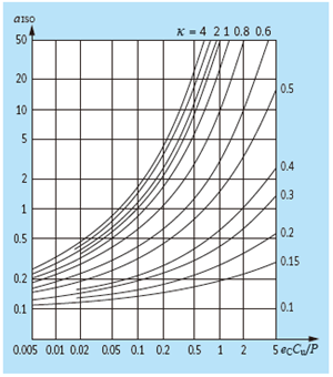

In the illustrations, information is provided on the life modification factor aISO of (from left to right) radial ball bearings, radial roller bearings, axial ball bearings and axial roller bearings.
Example calculation of L10mh
Same bearing and application as above: 6206C3
Cr = 21.6 kN
Cu = 0.795 kN
Fa = 250 N
Fr = 2000 N
n = 2000 rpm
High cleanliness of the surroundings
Lubricant viscosity at operating temperature 80°C of 14.37 mm²/s
X = 1, Y = 0, since Fa/Fr ≤ e
Pr = 2 kN
L10 = (21.6/2)3 = 1 259.71 x 10⁶ revolutions
L10h = 10 497.6 h
With Dpw < 100 mm follows eC = 0.6 – 0.8
With formula 5 it follows for v1 = 14.76 mm²/s
From this follows κ = 0.9
From the diagram for radial ball bearings, an aISO value of approx. 8 can be seen
From this follows for L10hm = 83 981 h
The calculation of L10mh using the example of the deep groove ball bearing 6206C3.
Other methods for calculating bearing life
In addition to the methods described here for determining the service life of a rolling bearing, there are other methods for calculating failure due to material fatigue. For example, when calculating the reference service life according to ISO TS 16281, the load distribution of the rolling element over its length is considered using a disc model. This method takes into account other influencing variables such as the operating clearance and misalignment of the bearing, but also the existing contact stresses of the respective rolling contacts. However, due to the immense computational effort, such a method is only suitable when using a calculation programme.
You may also be interested in
Lubrication
Nothing works without lubrication: Every bearing runs with grease or oil lubrication, which is the basic prerequisite for avoiding metallic contact of the bearing components,