Search
Close this search box.

Bearing mounting and the design of surrounding components

Overview

Summary

  • After calculation and selection of the bearing arrangement, the design of surrounding components must be carefully considered.
  • Rolling bearings are secured with the aid of mechanical elements such as locknuts, circlips (snap rings) or adapter sleeves.
  • The choice of the correct fits with shaft and housing depend on the operating conditions
  • In the context of bearing abutment dimensions, shoulder height and fillet radii are important

Generally speaking, a bearing is only as good as its environment. Who can perform at their best if they don’t feel comfortable in their surroundings? Have you already read our article on fixed and floating bearings? This chapter provides a good basis for bearing mounting and surrounding component design.

Shaft and housing design

After the correct bearings and bearing arrangement have been selected, the surroundings must now be considered. The most important criteria that need to be taken into account are listed below.

  • Selection of the bearing arrangement
  • Correct bearing mounting
  • Ensuring the mountability of the bearing (Important if you don’t want to make enemies during mounting).
  • Choosing the right fit
  • Determination of the correct bearing abutment dimensions (shoulder heights and corner radii)
  • Geometric accuracy of shaft and housing (Attention: The more accurate, the higher the costs!)
  • Determination of the maximum bearing misalignment in comparison to the permissible misalignment

At all times, the rolling bearing manufacturer’s specifications should be observed with regard to these criteria.

Securing of rolling bearings with mechanical elements

Information on choosing the right bearing arrangement can be found in the corresponding article. Let’s start with the correct mounting of the bearings on the shaft and in the housing. Rolling bearings can be secured with the help of various mechanical elements, including, for example, the use of lock nuts or retaining bolts or the use of a retaining ring (snap ring). For bearings with tapered bores, other bearing-specific accessories such as adapter sleeves and withdrawal sleeves can be used.

Inner ring lockOuter ring lockSnap ring
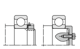
Rolling bearings can be fixed with the help of lock nuts or retaining bolts.Above is a classic fastening with lock nut, lock washer, snap ring, bearing cover and spacer ring.
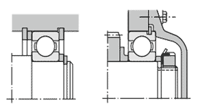
In this table you will see the fastening methods of rolling bearings that are generally in use.

With regard to the use of a retaining ring (snap ring), special attention must be paid to potential sources of error such as limit radii and bearing connection dimensions. Circlips simplify the construction. It is also important to know that retaining rings (snap rings) have certain disadvantages. They are not suitable for precision applications and equally unsuitable for absorbing high axial loads. 

Mounting with adapter sleeveMounting with withdrawal sleeveMounting with tapered shaft
Adapter sleeves and withdrawal sleeves are used for axial location of the bearing on cylindrical shafts.A split ring inserted into a groove on the shaft holds the rolling bearing in position with a split ring nut.
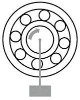
Further mounting options for rolling bearings are shown here for you.

The adapter sleeve is fixed by the frictional force between the shaft and the inner diameter of the sleeve. In addition, the position of the bearing on a cylindrical shaft can be freely selected when mounting with an adapter sleeve or withdrawal sleeve; both mounting variants are considered simple and process-safe. Mounting bearings with a tapered shaft is also an option. In this case, the split retaining ring is secured with a locknut or screw. The bearings (such as the spherical roller bearing in the illustration) can also be mounted easily and reliably by hydraulic means. According to the manufacturer’s instructions, the displacement path must be measured and, at the same time, always checked, just like the bearing clearance.

Selection of the correct tolerances for shaft and housing

After this brief overview of the various fixing options, we now come to the importance of tolerances for the shaft and housing. On the subject of bearing clearance and preload, terms such as bearing clearance and operating clearance have already been mentioned and it has also been explained how to calculate them. This chapter is now about choosing the right fits. The choice of theright” fit depends on the following considerations:

  • Shaft and housing material
  • Wall thickness
  • Surface texture
  • Operating conditions of the machine 

So, let’s get straight to the first important question: Tight fit or loose fit?

Load visualisationBearing ring  rotationBearing ring load Bearing seat fit

Fixed load

Inner ring rotates 

Outer ring static

Circumferential load for the inner ring

Point load for the outer ring 

Inner ring: Tight fit 

Outer ring: Loose fit
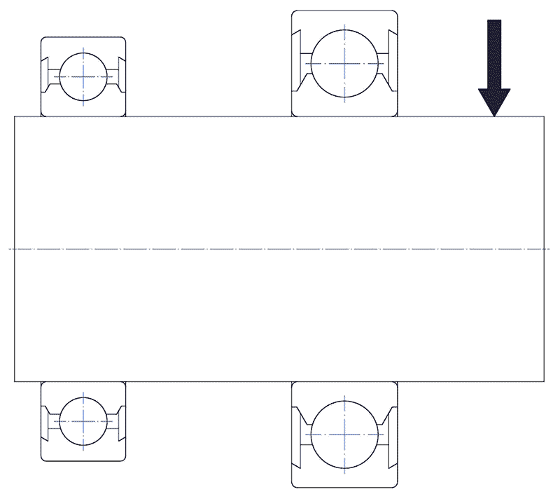
Circulating load

Inner ring static 

Outer ring rotates 

Fixed load

Inner ring static 

Outer ring rotates 

Point load for the inner ring 

Circumferential load for the outer ring 

Inner ring: Loose fit 

Outer ring: Tight fit 

Circulating load

Inner ring rotates 

Outer ring static 

This table shows you under what circumstances a fixed or loose fit is necessary. 

First it has to be clarified which of the two rings is rotating and which is static. Then it is checked which load is applied to the inner ring and which to the outer ring. An example: For the bearing unit shown, the fits for the two roller bearings are to be selected. Finally, the pulley is mounted on the shaft. The two bearings in question are a 6320C4 and a 6318C4 (manufacturer NTN).

You can visualise the bearing block in the example given like this.
Example bearing arrangement.

Which ring rotates? Correct, both inner rings. The outer rings, on the other hand, should not rotate. Does the inner ring have a point load? No, it has a circumferential load. Circumferential load means that the direction of the radial load acting on the inner ring is circumferential for the ring. Point load is present on both outer rings and means that the load only acts on a small point of the outer ring. The recommended fit is therefore: Inner ring = tight fit and outer ring = loose fit. Suggestions for suitable fits can be found in the catalogues of the rolling bearing manufacturers, for example at NTN.  For the current case, for example, taking into account a “normal load“, both shaft seats should have a k5 tolerance and an H7 tolerance should be selected for the housing seats.

Meaning of the bearing abutment dimensions

In addition to the bearing mounting itself, attention to the bearing abutment dimensions is crucial, with the shoulder height and corner radii playing a particularly important role.

Shoulder height and corner radius are important parts of the bearing abutment dimensions.

It is important that the height h of the bearing ring against the shaft and housing (left side of the illustration) is greater than the maximum permissible edge radius rs max of the bearing (right side of the illustration). Otherwise, the support of the bearing on the shaft and housing is not sufficient. It must also be taken into account that the fillet radius ra has a smaller value than the smallest permissible edge radius of the rolling bearing rs min.

There are situations in which the corner radius ra max is larger than the edge radii of the bearing. Among other things, this occurs when the shaft is to be strengthened or the contact height is not sufficient as a support surface for the bearing. In such cases it is appropriate to use spacer rings. Spacer rings are individually manufactured in such a way that correct contact between the ring and the rolling bearing on the shoulder of the shaft or housing is guaranteed.

In the illustration you can see technical drawings of a spacer ring. This is drawn in light grey.
The general rule for shafts and housing abutment heights is that both are always designed to be greater for axial bearings than for radial bearings.

When using thrust bearings, it must be ensured that the supporting surfaces of the bearing rings are sufficiently wide, taking into account the criteria of load and rigidity. For this purpose, there are corresponding dimension tables, for example, in NTN’s catalogue.

Accuracy of the shaft and housing bearing seats

Another key area for design of surrounding parts is the accuracy of the mating surfaces for the shaft and housing. In addition, the surface roughness and the perpendicularity of the bearing shoulders are taken into account.

PropertyShaftHousing
Dimensional accuracyIT6 (IT5)IT7 (IT5)

Roundness (max.)

Cylindricity

IT3IT4
Abutment squarenessIT3IT3

Fitting surface roughness

Ra

Small bearings0,8 µm1,6 µm
Medium ~ large bearings1,6 µm3,2 µm

In the table you will find useful specifications regarding shaft and housing tolerances. This table applies to normal operating conditions. (IT = basic tolerances).

Permitted inclination and misalignment

Shaft deflections, deviations in the finishing of shaft and housing as well as the smallest installation errors lead to a certain misalignment between the inner and outer ring of a rolling bearing. It is therefore important that in applications where misalignments can be comparatively high, adjustable-angle bearings such as self-aligning ball bearings, spherical roller bearings or insert bearings are used. Basically, it should be noted that the permissible misalignment depends on factors such as the bearing type, load conditions and operating clearance and thus varies depending on the application. The specified guide values should not be exceeded, otherwise there is a risk of bearing damage or problems with the cage.

Allowable bearing misalignment
Deep groove ball bearing1/1 000 ~ 1/300

Tapered roller bearing:

Single-row (standard)

Single-row (Ultage)

0

1/2 000

1/600

Angular contact ball bearing

Single-row

1/1 000

Needle bearing1/2 000

Cylindrical roller bearing

Bearing series 10, 2, 3, 4

Bearing series 22, 23

Ultage

Double-row

0

1/1 000

1/2 000

1/500

1/2 000


The permissible misalignment of various types of rolling bearings.

Permissible bearing inclination

Self-aligning ball bearing

Normal load

0

1/15

Thrust spherical roller bearing

Normal load

0

1/60 to 1/30

Spherical roller bearing 

Normal load or more 

Light load

1/115

1/30

Insert bearing1/60 to 1/30

Self aligning bearings are used in applications with relatively high misalignments.

You may also be interested in

Lifetime calculation

Damn, bearing damage! If you consider that rolling bearings are exposed to continuous pressure and shear stress, this is nothing unusual to begin with. What

Read more »

Sealing

During the design of a bearing assembly, the topic of sealing will always accompany you. In the following material, we will cover both integrated and

Read more »

Overview

Summary

  • After calculation and selection of the bearing arrangement, the design of surrounding components must be carefully considered.
  • Rolling bearings are secured with the aid of mechanical elements such as locknuts, circlips (snap rings) or adapter sleeves.
  • The choice of the correct fits with shaft and housing depend on the operating conditions
  • In the context of bearing abutment dimensions, shoulder height and fillet radii are important

Download all articles as a free eBook now!

SNR Wälzlager GmbH creates the information for this website with great care and endeavors to ensure that it is up-to-date, correct and complete. SNR Wälzlager GmbH assumes no liability and is not liable for any material or immaterial damage caused by the use of the service, unless it can be proven that it was caused by intent or gross negligence.